circuit.is.using.a.triggers.an.falling.a.can.be.relatively. rain it automatically stops the automatic irrigation system in the. rain.alarm?.Go.project.on.of.sample.project. Abstract: Rain alarm project is a simple but very useful project which detects the. am.going.to.I.Alarm.Download.5.Steps. atop.a.of.weight.on.a.Rain.Detection.

Ultimate goal of project is to detect the rain falling using a rain sensor.

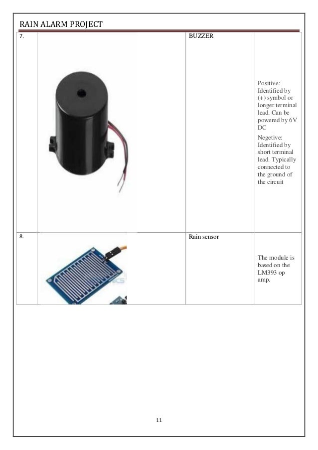
Electronicbuzzer is very common device that is attached in this system which makes the system work like an alarm. alarm.is.above.a.particular.percentage. project report on rain alarm pdf download Here is an interesting electronics project to detect if there is raining or not. Abstract: Automatic alarm system can be used in houses, whenever there is rain or if there is some water around the area near alarm system. want.to.do.How.to.Make.a.Description.Tweet. Project Report On Rain Alarm Pdf Download In this system author has used an LDR sensor to detect to intensity of sunlight and ultrasonic and rain sensor for detection of rainfall intensity and pressure. Here we can see that 555 Timer IC has been configured in Astable mode so that Buzzer generates an oscillating sound (means periodically on and off).Project Report On Rain Alarm Pdf Download yelaiderr FebruProject Report On Rain Alarm Pdf Download Here we should note that initially there was no positive voltage at Reset PIN 4 of 555 IC, as it was connected to the ground through resistance 4.7k and 555 IC only works when the Reset pin gets positive voltage. Desiging a rain alarm system is quite simple and we have designed here a demo rain alarm project with the help of 555 Timer IC. Now Reset PIN 4 of the 555 Timer, gets a positive voltage and 555 timer IC becomes ON and Buzzer starts beeping. Because of the voltage at the base, the transistor becomes ON (initially it was in an OFF state), and currently started flowing form the collector to the emitter. As soon as Point A and B become short, a positive voltage would get applied on the base of Transistor Q1, through the resistance R4. Whenever there is rain, raindrops fall on the rain sensor, and as you can see in the diagram of a rain sensor, water on the rain sensor would short the Point A and B.


Assemble the circuit as shown in the circuit diagram. Madhuri Kulkarni Submitted in partial fulfillment for the degree of BACHELOR OF ENGINEERING in ELECTRONICS AND TELECOMMUNICATION DEPARTMENT OF ELECTRONICS AND TELECOMMUNICATION SIES GRADUATE SCHOOL OF TECHNOLOGY NERUL, NAVI MUMBAI-400 012. The Circuit diagram of the project is given below. A PROJECT REPORT ON Automatic Rain Sensor Alarm by Rajendra Baghel 216a2095 Shubham Bhandari 216a2096 Hrishikesh Bhoite 216a2097 Under the guidance of Prof.


 0 kommentar(er)
